每天分享 Cadence 操作 · 反相器自动化
Cadence SKILL:创建反相器连接线并添加标签
创建 NMOS 与 PMOS 后,为输入网络添加 in 标签,再读取两只管子的 D 端口位置,自动连接输出网络并添加 out 标签。
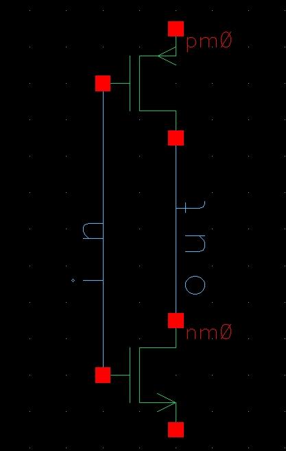
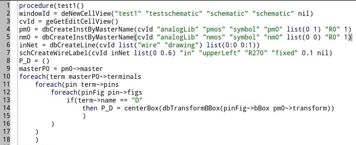
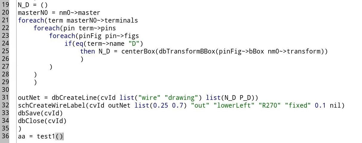
本文延续前一篇“创建 schematic 并放置管子”的流程:先创建并取得 cellView,放置 PMOS 与 NMOS,然后分别构建输入、输出网络。关键点是从实例 master 的 terminals 中找到 D 端 pin,并将 pin 图形的坐标转换到当前实例坐标系。
整体流程
- 01–03创建并放置器件创建 schematic,获取 cellView ID,放置 PMOS 与 NMOS。
- 04–05创建输入网络创建固定坐标的输入线,并添加 in 标签。
- 06–08定位 D 端并连接读取 PMOS 与 NMOS 的 D terminal 图形中心,转换为实例坐标后连线。
- 09添加输出标签为输出线添加 out 标签,最后保存并关闭。
1. 创建 Schematic 并取得 CellView
windowId = deNewCellView(
  "test1" "testschematic"
  "schematic" "schematic" nil
)
cvId = geGetEditCellView()
deNewCellView 创建并打开 schematic,随后通过 geGetEditCellView() 取得正在编辑的数据库对象。
2. 放置 PMOS 与 NMOS
pm0 = dbCreateInstByMasterName(
  cvId "analogLib" "pmos" "symbol"
  "pm0" list(0 1) "R0" 1
)
nm0 = dbCreateInstByMasterName(
  cvId "analogLib" "nmos" "symbol"
  "nm0" list(0 0) "R0" 1
)
PMOS 放在 (0 1),NMOS 放在 (0 0),方向均为 R0。
3. 创建输入线并添加 in 标签
inNet = dbCreateLine(
  cvId list("wire" "drawing")
  list(0:0 0:1)
)
schCreateWireLabel(
  cvId inNet list(0 0.6)
  "in" "upperLeft" "R270"
  "fixed" 0.1 nil
)
先按固定坐标创建输入线,再将标签 in 放在线上。标签的对齐方式、旋转角度和文字高度可按版式调整。
4. 获取 PMOS 的 D 端口位置
P_D = nil
masterP0 = pm0~>master
foreach(term masterP0~>terminals
  foreach(pin term~>pins
    foreach(pinFig pin~>figs
      if(term~>name == "D"
        then P_D = centerBox(
          dbTransformBBox(
            pinFig~>bBox pm0~>transform
          )
        )
      )
    )
  )
)
遍历 master 中的 terminals、pins 和 figures。找到名称为 D 的 terminal 后,将 pin 图形的 bounding box 按实例 transform 转换,再用 centerBox 得到中心坐标。
5. 获取 NMOS 的 D 端口位置
N_D = nil
masterN0 = nm0~>master
foreach(term masterN0~>terminals
  foreach(pin term~>pins
    foreach(pinFig pin~>figs
      if(eq(term~>name "D")
        then N_D = centerBox(
          dbTransformBBox(
            pinFig~>bBox nm0~>transform
          )
        )
      )
    )
  )
)6. 连接两个 D 端并添加 out 标签
outNet = dbCreateLine(
  cvId list("wire" "drawing")
  list(N_D P_D)
)
schCreateWireLabel(
  cvId outNet list(0.25 0.7)
  "out" "lowerLeft" "R270"
  "fixed" 0.1 nil
)
使用刚刚计算得到的 N_D 与 P_D 创建输出连接线,再在线上添加 out 标签。
7. 保存并关闭
dbSave(cvId)
dbClose(cvId)
下期预告
探索 SKILL 之外的 IC 自动化工具
下一篇将探索一种便于 IC 自动化的新语言或工具;Cadence SKILL 系列也会持续更新。
查看更多自动化教程